
Introduction 
A wide variety of cheap gas and chemical sensors are available on Aliexpress and other Chinese e-commerce stores. A common style of sensor is a 6 pin circular model, which follows the naming convention of MQ with a number designating what kind of gas the sensor is designed to detect. These sensors fall into the category of being metal oxide gas sensors. Some of these sensors include the MQ-7 (Carbon Monoxide), MQ-4 (Methane), MQ-2 (Smoke), MQ-137 (Ammonia), and the MQ-3, an alcohol sensor which I used for my portable breathalyzer. These metal oxide sensors, act as a chemisresistor, since they change resistance based on the ppm of whatever chemical the sensor is designed to detect. This means that the value obtained from the sensor is an analog voltage that is proportional to the ppm of the aforementioned gas. A diagram of the inner MOS of an MQ3 sensor is shown below.
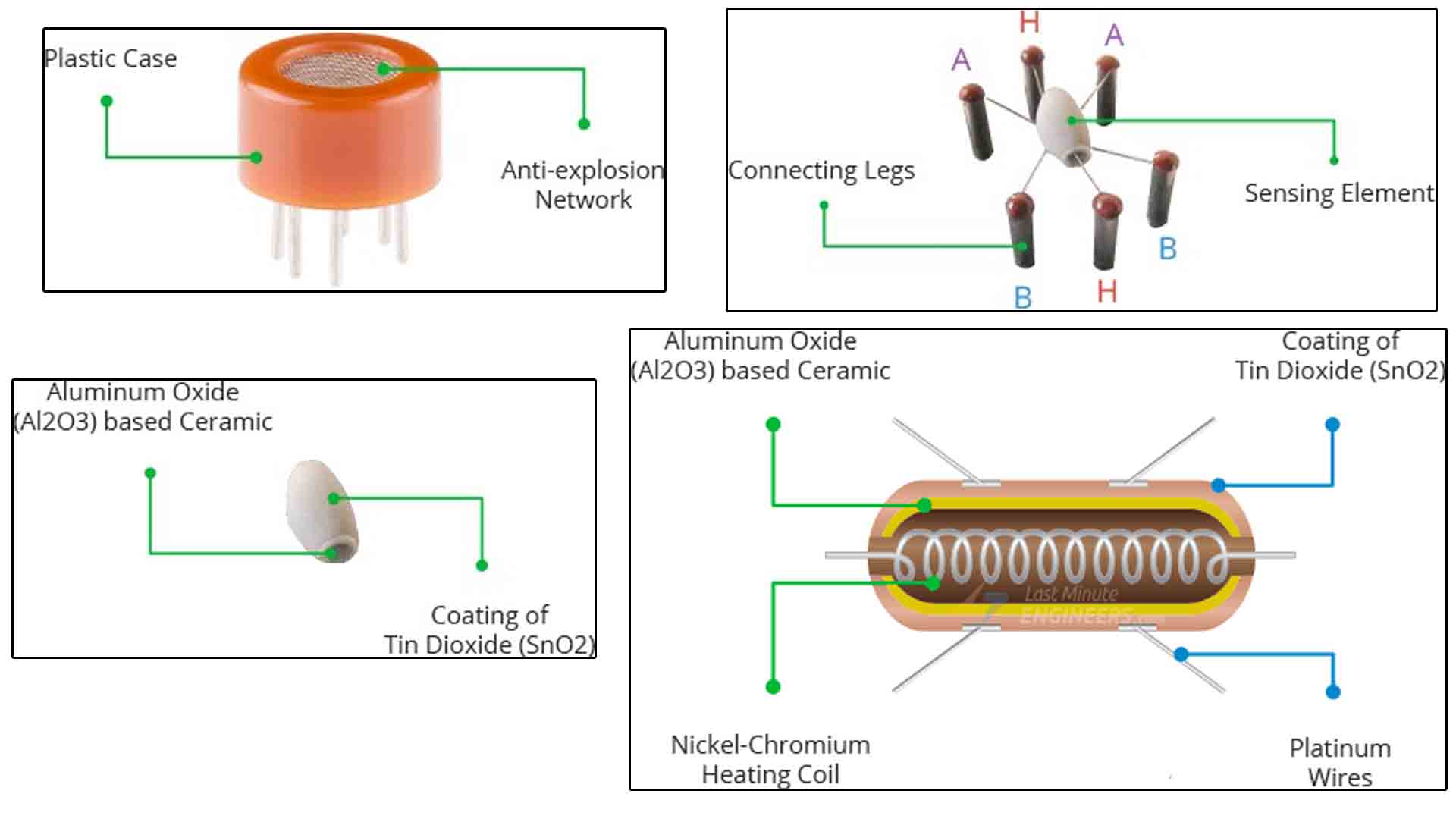
Image courtesy of Electronoobs.com
Case Design 
For designing my portable “breathalyzer”, I decided to use a cheap MQ3 module, a Wemos D1 Mini, and an 80x160 ST7735 display. All of these components are cheap and easy to purchase on Aliexpress. I used the same battery and boost converter that I used in my Retropie handheld.

Assembled view of the case

Where the components go
Click here for the STLs and code
For the display, I used the TFT_eSPI library for the graphics. To configure the library to work for the 80x160 ST7735 display you need to copy the following settings into the User_Setup.h file that is in the TFT_eSPI library directory.
// See SetupX_Template.h for all options available

#define ST7735_DRIVER


#define TFT_WIDTH  80
#define TFT_HEIGHT 160


#define ST7735_GREENTAB160x80

// For ST7735, ST7789 and ILI9341 ONLY, define the colour order IF the blue and red are swapped on your display
// Try ONE option at a time to find the correct colour order for your display

//  #define TFT_RGB_ORDER TFT_RGB  // Colour order Red-Green-Blue
#define TFT_RGB_ORDER TFT_BGR  // Colour order Blue-Green-Red

// For NodeMCU - use pin numbers in the form PIN_Dx where Dx is the NodeMCU pin designation
#define TFT_CS   PIN_D8  // Chip select control pin D8
#define TFT_DC   PIN_D6  // Data Command control pin
#define TFT_RST  PIN_D4  // Reset pin (could connect to NodeMCU RST, see next line)
//#define TFT_RST  -1    // Set TFT_RST to -1 if the display RESET is connected to NodeMCU RST or 3.3V


#define LOAD_GLCD   // Font 1. Original Adafruit 8 pixel font needs ~1820 bytes in FLASH
#define LOAD_FONT2  // Font 2. Small 16 pixel high font, needs ~3534 bytes in FLASH, 96 characters
#define LOAD_FONT4  // Font 4. Medium 26 pixel high font, needs ~5848 bytes in FLASH, 96 characters
#define LOAD_FONT6  // Font 6. Large 48 pixel font, needs ~2666 bytes in FLASH, only characters 1234567890:-.apm
#define LOAD_FONT7  // Font 7. 7 segment 48 pixel font, needs ~2438 bytes in FLASH, only characters 1234567890:.
#define LOAD_FONT8  // Font 8. Large 75 pixel font needs ~3256 bytes in FLASH, only characters 1234567890:-.
//#define LOAD_FONT8N // Font 8. Alternative to Font 8 above, slightly narrower, so 3 digits fit a 160 pixel TFT
#define LOAD_GFXFF  // FreeFonts. Include access to the 48 Adafruit_GFX free fonts FF1 to FF48 and custom fonts

#define SMOOTH_FONT


// #define SPI_FREQUENCY  20000000
#define SPI_FREQUENCY  27000000
// #define SPI_FREQUENCY  40000000

// #define SPI_TOUCH_FREQUENCY  2500000


// #define SUPPORT_TRANSACTIONS
Wiring 
The wiring for this device is pretty simple. For shifting the 0-5V analog output of the MQ3 sensor to having a safe maximum voltage for the analog input of the ESP8266, I used a simple voltage divider. Other than that, the wiring for everything is fairly standard. It should be noted that P+ and P- are the BMS IO for the battery. If you are using a battery without a BMS, do not directly connect the battery to power input and output. A BMS is mandatory when using lithium ion or lithium polymer batteries. The schematic is shown below.

Assembly 
For assembly, I used hex button M3 screws for fastening the case together and mounting the MQ3 sensor. For keeping the screen in place, I experimented with having a plastic column support the screen and sandwiching it in place with the lid. This worked out surprsingly well and prevented me from having to use unnecessary screws. To keep the Wemos D1 Mini, there is a section behind the MQ3 sensor where I fit the board into the indentation in the case. I used double sided tape to keep it fixed in. I didn’t import a model of this into the Fusion 360 drawing, but there is also a slide switch (the same model used in the Retropie build) that fits into the side hole on the white part of the case. The hole in the orange part is for the micro USB breakout board (again, from the Retropie build).
Usage 
This is NOT a medically accurate breath alcohol sensor. Do not use this to gauge how safe it would be for you to operate a motor vehicle. The purpose of this project is to be used as a fun way to see how intoxicated you are. For legal purposes (I am 19 as of creating this device and the drinking age in the United States is 21) I only tested this sensor with isopropyl alcohol so you may need to adjust the thresholds in the Arduino script.